Industry News

Turning processing is a material removal process that manufactures cylindrical parts by rotating the workpiece and removing material using a fixed cutting tool. In the field of machining, turning is one of the most common and fundamental operations, accounting for approximately 25% of all machining operations. The lathe, as the core equipment for performing turning processing, can machine various features including external diameters, internal holes, end faces, threads, and grooves.
The historical evolution of lathes dates back to ancient Egyptians using two-person operated bow lathes. During the Industrial Revolution, Henry Maudslay invented the screw-cutting lathe in 1797, establishing the basic structure of modern lathes. In the 1950s, the first CNC lathe emerged, completely revolutionizing the manufacturing industry. Today, CNC turning centers are equipped with advanced features such as multiple axes, multiple tools, and automatic loading/unloading, achieving machining accuracy up to 0.001mm level.
The strategic position of turning processing in modern manufacturing remains irreplaceable in aerospace, automotive manufacturing, medical devices, mold processing, and other fields. According to statistics, over 60% of metal parts produced globally each year require some form of turning processing. With the advent of Industry 4.0, intelligent turning systems can monitor cutting force, vibration, temperature and other parameters in real-time, achieving adaptive control and significantly improving machining efficiency and quality stability.
To understand the precision of turning, one must first understand the mechanical structure of the lathe. The Headstock contains the drive motor and spindle, serving as the power source for the entire machine. The Bed is typically made of high-strength cast iron, designed to absorb cutting vibrations. The Tailstock is used to support long shaft parts, preventing run-out during rotation. Modern CNC lathes are also equipped with an Automatic Turret, which can switch between different inserts in milliseconds, significantly shortening machining cycles.
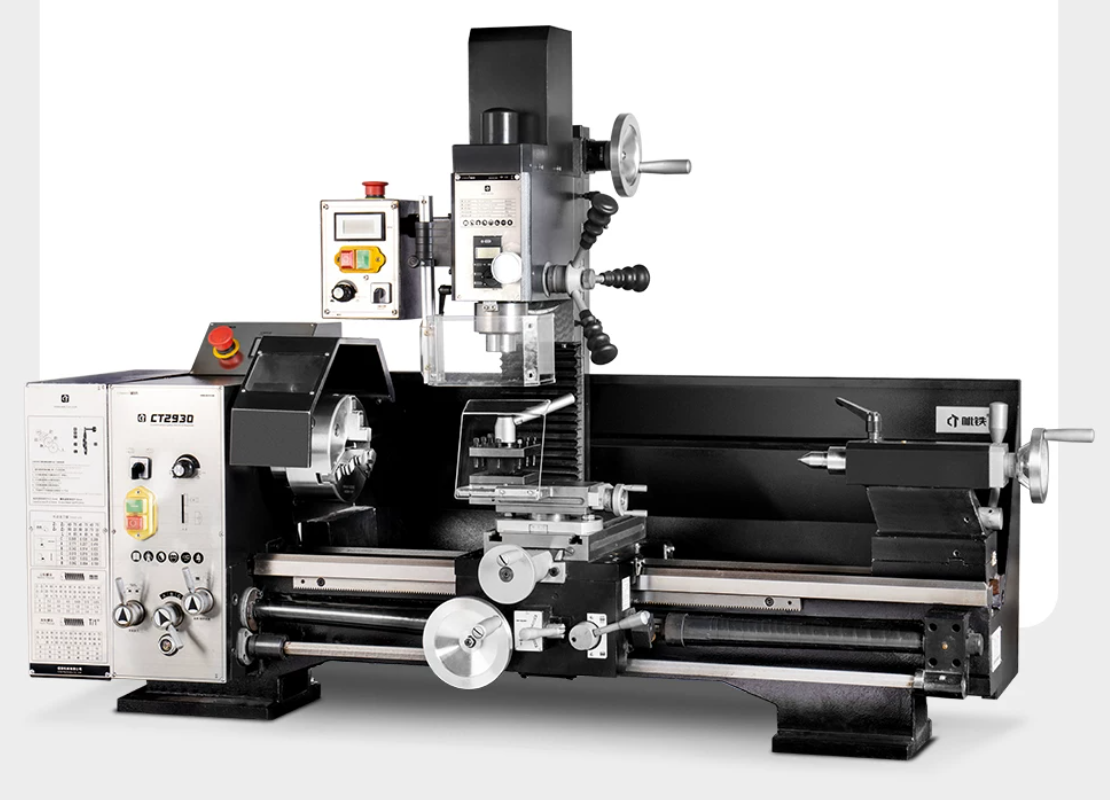
The conventional horizontal lathe is the most traditional type, with the spindle arranged horizontally, suitable for machining shaft-type and disc-type parts. Although operation relies on manual skills, it is still widely used in small batch production and maintenance workshops. Its spindle bore is typically 50-100mm, with maximum machining length reaching over 3000mm.
CNC lathes automatically execute machining programs through computer control systems, significantly reducing the need for manual intervention. Entry-level CNC lathes are typically equipped with two axes (X-axis and Z-axis), while advanced models can be equipped with C-axis, Y-axis, and even subspindles, enabling multiple operations in a single setup. Modern CNC lathes can achieve spindle speeds of 6000-12000rpm and rapid traverse rates of 30m/min.
Vertical lathes have the spindle arranged vertically with a horizontally positioned worktable, particularly suitable for machining large-diameter, short-length heavy workpieces such as large gears, hubs, and flanges. The vertical structure utilizes gravity to stabilize the workpiece, effectively reducing clamping deformation, with maximum machining diameters reaching over 5000mm.
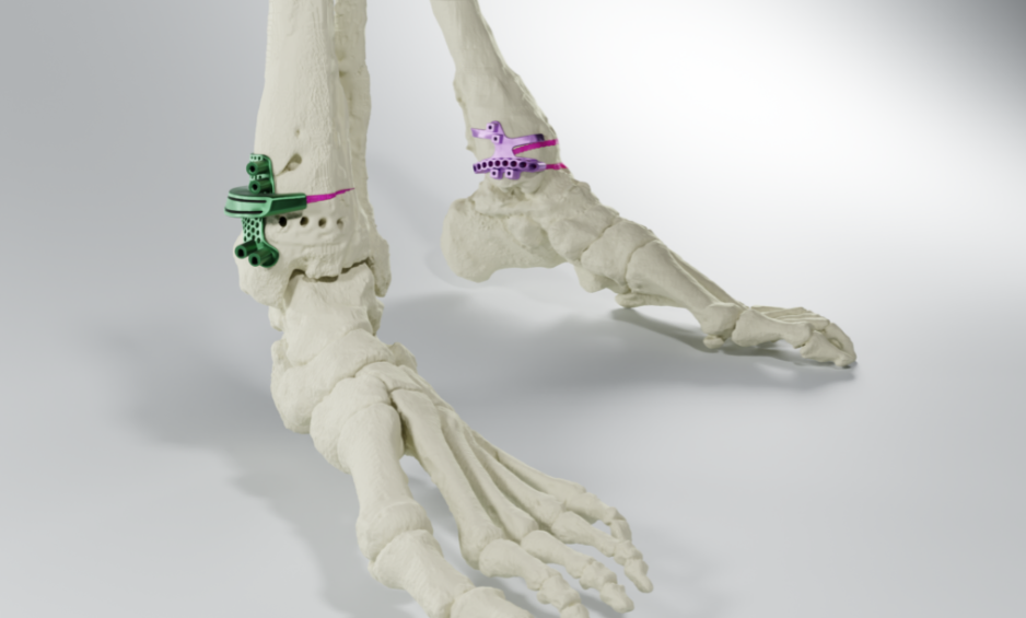
Swiss-type automatic lathes (also known as sliding headstock lathes) are equipped with a guide bushing structure where material is fed through the guide bushing, and tools cut close to the guide bushing position. This design eliminates overhang issues, making it suitable for machining slender precision parts such as medical bone screws, electronic connectors, and watch components. Machining diameters typically range from 3-32mm, with length tolerances controllable within ±0.005mm.
Turning centers are the most powerful type of lathe, integrating compound machining capabilities such as milling, drilling, and tapping on top of traditional turning functions. Turning centers equipped with live tooling and Y-axis can achieve true “one setup, complete machining,” combining multiple operations and significantly reducing setup errors and auxiliary time.
Turning machining is the process of cutting the workpiece with a fixed tool while the workpiece rotates on a lathe. The basic principle of turning involves the interaction between the cutting tool and the workpiece, utilizing the tool’s geometry such as rake angle and clearance angle. Factors such as cutting forces, cutting temperature, and tool material selection all impact the effectiveness of the turning operation and the quality of the parts. Turning can handle materials including metals, plastics, and alloys, and is widely used for shaping parts, finishing operations, and some internal hole machining.
Turning is not limited to diameter reduction. Facing is used to produce smooth end planes; Grooving cuts narrow slots into the workpiece surface, commonly used for O-rings or circlips; Boring involves enlarging existing holes to improve coaxiality and dimensional accuracy. Additionally, Threading utilizes the synchronous control of the CNC system to machine complex single-start, multi-start, and variable-pitch threads.
Cutting speed refers to the relative linear speed between the workpiece machining surface and the tool, measured in m/min. Selecting appropriate cutting speed directly affects machining efficiency, tool life, and surface quality. For ordinary carbon steel, recommended cutting speed is 80-150m/min; for stainless steel, 60-120m/min; for aluminum alloy, up to 300-800m/min; for titanium alloy, it needs to be controlled at 40-80m/min.
Feed rate represents the distance the tool moves along the machining direction per revolution of the spindle, measured in mm/r. Roughing typically uses larger feed rates (0.2-0.5mm/r) to increase material removal rates; finishing uses small feed rates (0.05-0.15mm/r) to achieve good surface finish. Excessive feed rate causes dramatic increase in cutting force, leading to vibration and tool breakage; insufficient feed rate reduces efficiency and may cause work hardening.
Depth of cut is the radial depth that the tool penetrates into the workpiece, affecting cutting force and material removal rate. During roughing, depth of cut can reach 3-8mm or even larger; finishing is controlled at 0.2-0.5mm. Note that the depth of cut should not exceed 60%-70% of the insert’s cutting edge length, otherwise tool failure may occur.
Cutting force consists of three directional components: main cutting force (tangential force), radial force, and axial force. The main cutting force is used to calculate required power using the formula: P = (Fc × Vc) / 60000, where P is power (kW), Fc is main cutting force (N), and Vc is cutting speed (m/min). Experience shows that turning carbon steel requires approximately 0.06-0.1kW power per cubic centimeter of material removed.
Tool material classification for turning has evolved from carbon tool steel to high-speed steel, carbide, ceramic, CBN (Cubic Boron Nitride), and PCD (Polycrystalline Diamond). Carbide is currently the most widely used tool material, occupying approximately 70% market share. CBN tools are suitable for machining hardened steel (HRC45-65), while PCD tools are the first choice for machining non-ferrous metals such as aluminum alloy and copper alloy.
The international standard ISO 1832 specifies the coding system for indexable inserts, typically consisting of 10-12 characters. For example, in CNMG120408-PM, each character means: C (insert shape – 80° diamond), N (relief angle – 0°), M (tolerance class), G (chip breaker type), 12 (cutting edge length), 04 (insert thickness), 08 (nose radius), PM (application range). Understanding this coding system is crucial for correct insert selection.
Chip breaker design principles are key features controlling chip flow and fracture. Proper chip breaker design can break continuous chips into small segments, avoiding wrapping around the workpiece or tool. Based on machining conditions, chip breakers are divided into three types: small rake angle chip breakers for finishing (fine chips), large rake angle chip breakers for roughing (robust chips), and general-purpose chip breakers. The latest 3D chip breaker technology can adapt to a wider range of cutting parameters.
Coating technology significantly extends tool life and improves cutting performance. Mainstream coatings include: TiN (Titanium Nitride, gold color), TiCN (Titanium Carbonitride, blue-gray), TiAlN (Titanium Aluminum Nitride, purple-black), AlTiN (Titanium Aluminum Nitride variant, dark purple), and nanocomposite coatings. TiAlN coating stands out in high-temperature cutting due to its excellent thermal stability and oxidation resistance, with applicable temperatures up to 800-1000°C.
A certain automotive transmission shaft, material 20CrMnTi alloy steel, diameter Φ45mm, length 280mm, accuracy requirements: external diameter tolerance IT6 grade (±0.013mm), coaxiality Φ0.02mm, surface roughness Ra1.6μm. Process plan: 1) Rough turn external diameter and end face, leaving 0.8mm allowance; 2) Quenching and tempering to hardness 28-32HRC; 3) Semi-finish turning, leaving 0.2mm allowance; 4) Finish turn external diameter to size; 5) Mill keyway; 6) Surface carburizing and quenching to HRC58-62; 7) Grind to final dimensions.
The thin-wall bearing ring has a wall thickness of only 2.5mm, outer diameter Φ120mm, material GCr15 bearing steel. The machining difficulty lies in the thin-wall structure’s tendency to deform. Solutions: 1) Use soft jaws for clamping, increasing contact area; 2) Use large nose radius inserts (R1.2mm) to distribute cutting force; 3) Reduce cutting parameters (Vc=80m/min, f=0.08mm/r, ap=0.3mm); 4) Add auxiliary support (sector-shaped jaws); 5) Use two-setup finishing to eliminate residual stress deformation. Final roundness controlled within 0.005mm.
Titanium alloy hip joint stem part, material Ti6Al4V ELI, dimensional accuracy ±0.01mm, surface roughness requirement Ra0.4μm. Titanium alloy machining difficulties include poor thermal conductivity, low elastic modulus, and high chemical reactivity. Process key points: 1) Use sharp-edge PVD coated carbide inserts; 2) Adopt high cutting speed low feed strategy (Vc=60m/min, f=0.05mm/r); 3) Sufficient coolant pressure (70bar) and high flow rate (20L/min); 4) Use Minimum Quantity Lubrication (MQL) to assist chip evacuation; 5) Use cryogenic cooling technology (liquid nitrogen -196°C) to further control machining zone temperature.
With the advancement of technology, lathe technology is constantly evolving. Future lathes will become more intelligent and automated, integrating more sensors and feedback systems to monitor and optimize the machining process in real-time. The combination of CNC technology and artificial intelligence will further improve machining precision and efficiency. Additionally, innovations in lathe materials and cutting tool technologies will continue to drive the development of turning machining technologies.
The mechanical lathe plays a crucial role in modern manufacturing and is widely used across various industries. As technology advances, turning machining technology will continue to innovate, with the application of new technologies and materials driving the transformation of the lathe industry. In the future, lathe technology will become more intelligent and automated, supporting the manufacturing of more complex components. For manufacturing enterprises, mastering lathe technology and keeping up with new trends will be key to maintaining competitiveness.

Why Choose SLS 3D Pr
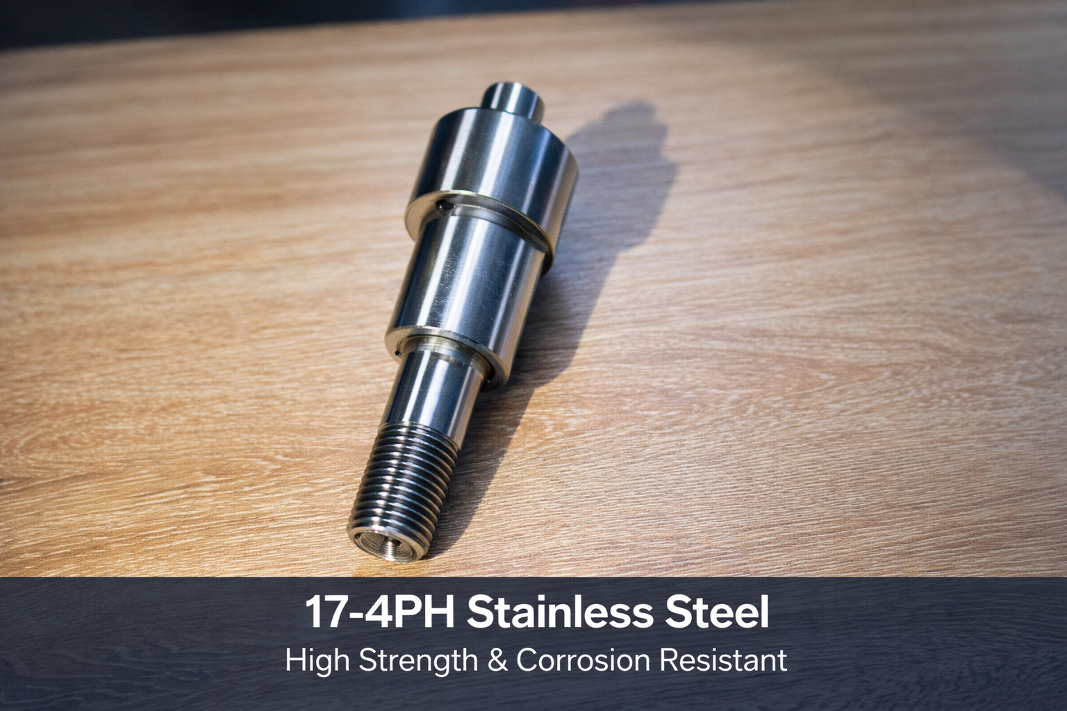
In today’s industrial manufacturing sector, the selection of materials directly determines the performance, lifespan, and cost-effectiveness of the final product. Among numerous high-performance metal materials, 17-4 Stainless Steel (also known as 17-4 PH) has become one of the preferred materials for the aerospace, medical device, petrochemical, and high-end mechanical manufacturing industries due to its unique precipitation hardening characteristics. As a martensitic precipitation hardening stainless steel, 17-4 not only possesses the inherent corrosion resistance of stainless steel but also achieves extremely high strength and hardness through heat treatment. This dual advantage allows it to maintain excellent stability even in extreme environments.